- 您现在的位置:买卖IC网 > Sheet目录1213 > EVAL-AD1939AZ (Analog Devices Inc)BOARD EVAL FOR AD1939
�� �
�
�UG-040�
�Evaluation� Board� User� Guide�
�PLL� SELECT�
�C120�
�R72�
�C60�
�R73�
�C63�
�C61�
�C65�
�TP26�
�R129�
�C125�
�R138�
�JP15�
�C131�
�IN1L�
�TP25�
�C69�
�R84�
�U12�
�R85�
�C64�
�C67�
�TP28�
�IN1L+�
�IN1L–�
�VREF� SELECT�
�S1�
�C74�
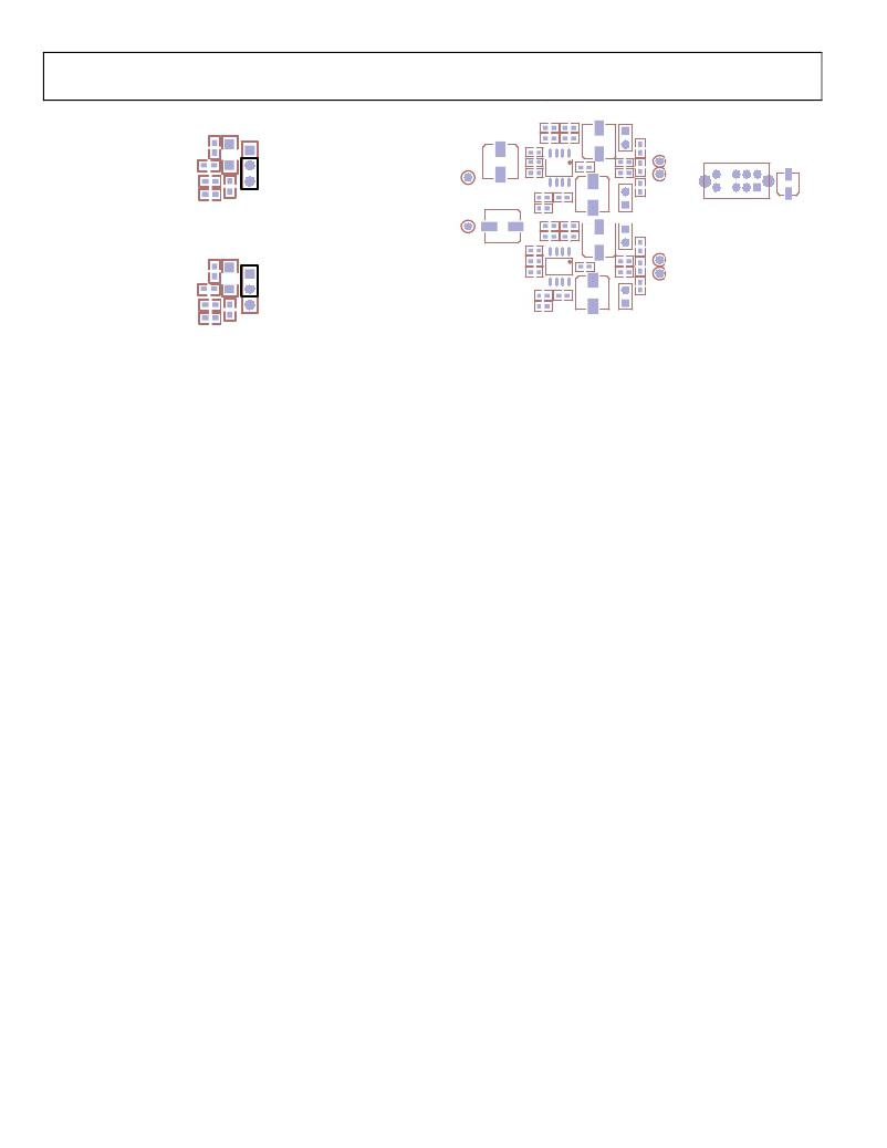
�Figure� 14.� MCLK� Loop� Filter� Selected�
�R86�
�R87�
�C80�
�PLL� SELECT�
�C120�
�TP30�
�IN1R�
�C76�
�C77�
�C82�
�C83�
�TP32�
�IN1R+�
�R129�
�U14�
�C99�
�C88�
�TP34�
�IN1R–�
�C125�
�R107�
�R138�
�JP15�
�R106�
�C131�
�Figure� 15.� LRCLK� Loop� Filter� Selected�
�Normally,� the� MCLK� filter� is� the� default� selection;� it� is� also�
�possible� to� use� the� register� control� window� to� program� the�
�PLL� to� run� from� the� LRCLK.� In� this� case,� the� jumper� must�
��CONNECTING� AUDIO� CABLES�
�Analog� Audio�
�The� analog� inputs� and� outputs� use� 3.5� mm� TRS� jacks;� they� are�
�configured� in� the� standard� configuration:� tip� =� left,� ring� =� right,�
�sleeve� =� ground.� The� analog� inputs� to� IN1� and� IN2� generate�
�0� dBFS� from� a� 1� V� rms� analog� signal.� The� on-board� buffer�
�circuit� creates� the� differential� signal� to� drive� the� ADC� with�
�2� V� rms� at� the� maximum� level.� The� DAC� puts� out� a� 1.8� V� rms�
�differential� signal;� this� signal� becomes� single-ended� for� the� OUT�
�connectors.� There� are� test� points� that� allow� direct� access� to� the�
�ADC� and� DAC� pins;� note� that� the� ADC� and� DAC� have� a�
�common-mode� voltage� of� 1.5� V� dc.� These� test� points� require�
�proper� care� so� that� improper� loading� does� not� drag� down� the�
�common-mode� voltage,� and� the� headroom� and� performance� of�
�the� part� do� not� suffer.�
�The� ADC� buffer� circuit� is� designed� with� a� switch� (S1)� that�
�allows� the� user� to� change� the� voltage� reference� for� all� of� the�
�amplifiers.� GND,� CM,� and� FILTR� can� be� selected� as� a� reference;�
�it� is� advisable� to� shut� down� the� power� to� the� board� before�
�changing� this� switch.� The� CM� and� FILTR� lines� are� very�
�sensitive� and� do� not� react� well� to� a� change� in� load� while� the�
�AD1937/AD1939� is� active.� A� series� of� jumpers� allows� the� user�
�to� dc-couple� the� buffer� circuit� to� the� ADC� analog� port� when�
��Figure� 16.� VREF� Selection� and� DC� Coupling� Jumpers�
�Digital� Audio�
�There� are� two� types� of� digital� interfacing,� S/PDIF� and� discrete�
�serial.� The� input� and� output� S/PDIF� ports� have� both� optical� and�
�coaxial� connectors.� The� serial� audio� connectors� use� 1� � 2� 100� mil�
�spaced� headers� with� pins� for� both� signal� and� ground.� The�
�LRCLK,� BCLK,� and� SDATA� paths� are� available� for� both� the�
�ADC� and� DAC� on� the� HDR1� and� HDR2� connectors.� Each� has� a�
�connection� for� MCLK;� each� HDR� MCLK� interface� has� a� switch�
�to� set� the� port� as� an� input� or� output,� depending� on� the� master�
�or� slave� state� of� the� AD1937/AD1939� .�
�SWITCH� AND� JUMPER� SETTINGS�
�Clock� and� Control�
�The� AD1937/AD1939� are� designed� to� run� in� standalone� mode�
�at� a� sample� rate� (f� S� )� of� 48� kHz,� with� an� MCLK� of� 12.288� MHz�
�(256� � f� S� ).� In� standalone� slave� mode,� both� ADC� and� DAC� ports�
�must� receive� valid� BCLK� and� LRCLK.� The� AD1937/AD1939�
�can� be� clocked� from� either� the� S/PDIF� receiver� or� the� HDR1�
�connector;� the� ADC� BCLK� and� LRCK� port� sources� are� selected�
�with� SW2,� Position� 2� and� Position� 3.� For� S/PDIF� master,� both�
�switches� should� be� off.� For� HDR1,� SW2,� Position� 3,� should� be�
�on� (see� the� detail� in� Figure� 17� and� Figure� 18).� The� DAC� BCLK�
�and� LRCK� port� sources� are� selected� with� SW2,� Position� 5� and�
�Position� 6.� For� S/PDIF� master,� both� switches� should� be� off.� For�
�HDR1,� SW2,� Position� 6,� should� be� on.� Note� that� HDR2� is� not�
�implemented� in� the� CPLD� routing� code.�
�It� is� also� possible� to� configure� the� AD1937/AD1939� ADC�
�BCLK� and� LRCK� ports� to� run� in� standalone� master� mode;�
�moving� J5� to� SDA/1,� as� shown� in� Figure� 3,� changes� the� state� of�
�the� AD1937/AD1939.� Setting� SW2,� Position� 2� and� Position� 5,� to�
�on� selects� the� proper� routing� to� both� the� S/PDIF� receiver� and�
�the� HDR1� connector.� In� this� mode,� the� AD1937/AD1939� ADC�
�port� generates� BCLK� and� LRCLK� when� given� a� valid� MCLK.�
�Rev.� 0� |� Page� 6� of� 32�
�发布紧急采购,3分钟左右您将得到回复。
相关PDF资料
EVAL-AD5172SDZ
BOARD EVAL FOR AD5172
EVAL-AD5252SDZ
BOARD EVAL FOR AD5252
EVAL-AD5254SDZ
BOARD EVAL FOR AD5254
EVAL-AD5932EBZ
BOARD EVAL FOR AD5932
EVAL-AD74111EBZ
BOARD EVAL FOR AD74111
EVAL-AD7741/42EBZ
BOARD EVAL FOR AD7741/7742
EVAL-AD8003-3CPEZ
BOARD EVALUATION AD8003-3CPEZ
EVAL-AD9830EBZ
BOARD EVALUATION AD9830
相关代理商/技术参数
EVAL-AD1939EB
制造商:Analog Devices 功能描述:EVAL - Bulk
EVAL-AD1940AZ
功能描述:BOARD EVAL AD1940 SIGMADSP RoHS:是 类别:编程器,开发系统 >> 评估演示板和套件 系列:SigmaDSP® 标准包装:1 系列:PCI Express® (PCIe) 主要目的:接口,收发器,PCI Express 嵌入式:- 已用 IC / 零件:DS80PCI800 主要属性:- 次要属性:- 已供物品:板
EVAL-AD1940EB
制造商:Analog Devices 功能描述:DEV TOOLS, SIGMADSPTM MULTICH 28BIT AUD PROCESSOR - Bulk
EVAL-AD1940MINIB
制造商:Analog Devices 功能描述:SIGMADSP EVAL BD - Bulk 制造商:Rochester Electronics LLC 功能描述:
EVAL-AD1940MINIBZ
功能描述:BOARD EVAL AD1940 MINI SIGMADSP RoHS:是 类别:编程器,开发系统 >> 评估演示板和套件 系列:SigmaDSP® 标准包装:1 系列:PSoC® 主要目的:电源管理,热管理 嵌入式:- 已用 IC / 零件:- 主要属性:- 次要属性:- 已供物品:板,CD,电源
EVAL-AD1941EB
制造商:Analog Devices 功能描述:EVAL BD SIGMADSPMULTICHANAUDIO PROCESSOR - Bulk
EVAL-AD1953EB
制造商:Analog Devices 功能描述:EVAL BRD FOR 3 CH 24 BIT SIG-PROCESS DAC - Bulk 制造商:Analog Devices 功能描述:EVALUATION KIT ((NS))
EVAL-AD1953EBZ
制造商:Analog Devices 功能描述:EVAL BRD FOR 3 CH 24 BIT SIG-PROCESS DAC - Bulk